Cargadora FrontalH310 MSL
- Sistema de auto nivelación Cargador compatible con diferentes familias de Tractores.
- Soporte Universal (Global Carrier).
- Mayor altura de levante.
- Líneas de aceite ocultas para una mayor protección y visibilidad.

Los Brazos de Levante de los Cargadores maximizan la visibilidad del operador mientras que proporcionan la fuerza para soportar muchos años de uso rudo. Es compatible con diferentes familias de tractores y cuenta con variedad de funciones hidráulicas para una mayor productividad.
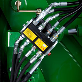 Conexión hidráulica de punto único en tractor serie 6 (posición cerrada)
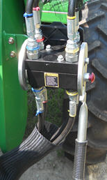 Conexión hidráulica de punto único en tractor serie 5 (posición cerrada)
Los cargadores frontales 540M y H310 pueden configurarse con una conexión hidráulica de punto único que también incorpora el punto de conexión para cualquier necesidad eléctrica. Para desconectar la conexión hidráulica entre el cargador frontal y el tractor, es necesario aliviar la presión de aceite del sistema hidráulico del tractor.
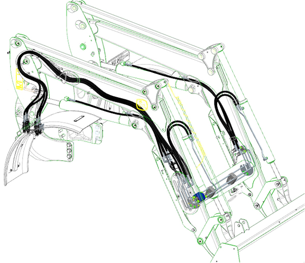 Tuberías de aceite ocultas a través del brazo de la barra de pulverización
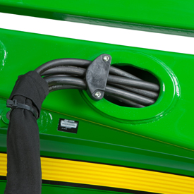 Tuberías de aceite dirigidas a través del brazo de la barra de pulverización
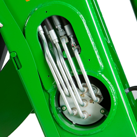 Tuberías de aceite dirigidas a través del tubo de torque
A lo largo del tiempo, la anchura incrementada en los cofres del tractor ha ocasionado problemas con el espacio disponible para operar las tuberías de aceite tradicionales de un cargador frontal a lo largo de la barra de pulverización, haciéndolas más susceptibles a daños.
Para mejorar esta situación, las tuberías de aceite han sido dirigidas a través del brazo de la barra de pulverización y el tubo de torque mejorando la protección de la línea y la apariencia del cargador frontal.
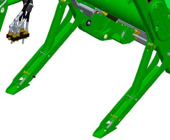 Pies de estacionamiento

Los cargadores frontales de John Deere se quitan y reinstalan fácilmente en los tractores, sin necesidad de usar herramientas. El sistema de estacionamiento permite quitar o acoplar el cargador frontal al tractor en minutos, sin necesidad de herramientas.
Para quitar o estacionar el cargador frontal, aplique presión ligera hacia abajo en el brazo del cargador con el cucharón vacío a un ángulo aproximado de 30 grados. Con el tractor en la posición de estacionamiento, instale los pedestales de estacionamiento y coloque los pasadores del mástil en la posición abierta.
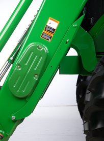 Pedestal de estacionamiento en posición de almacenamiento
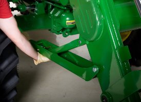 Extracción del pedestal de estacionamiento
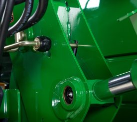 Pasador de mástil en posición cerrada
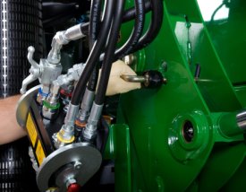 Girar el pasador del mástil a la operación abierta
Utilizando el circuito del brazo con el tractor en neutro, gire el mástil hacia delante hasta que éste haya girado más allá de la posición del pasador en el bastidor de montaje; para ello extienda el cilindro de elevación. Ahora, mediante la utilización del circuito del cucharón, voltear hacia atrás el cucharón hasta extraer el brazo de izado de la cavidad y se despejarán los neumáticos.
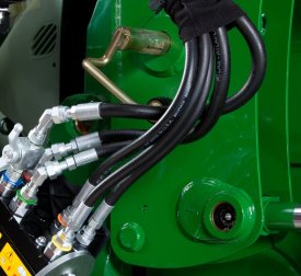 Pasador de mástil en posición abierta
 Los mástiles giran hacia adelante, luego el cucharón se voltea hacia atrás
Con el tractor en estacionamiento, apague el motor y alivie la presión hidráulica como se indica en el tractor (girando el joystick). Desconecte o abra el conector hidráulico de punto único (o extraiga los acopladores si no hay punto único instalado).
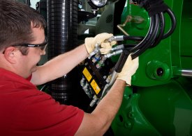 Desconecte/abra la conexión hidráulica de punto único
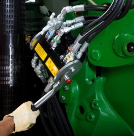 Desconecte/abra las conexiones hidráulicas de punto único
Almacene el cargador frontal a la mitad del conector de punto único o las mangueras, y retírese del cargador frontal.
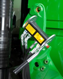 Sistema hidráulico de punto único desconectado

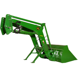 Cargador frontal estacionada
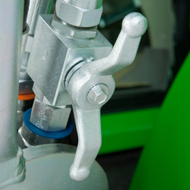 Válvula de cierre hidráulico (posición abierta)
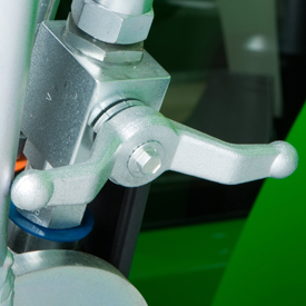 Válvula de cierre hidráulico (posición cerrada)
Se incluye una válvula de cierre hidráulico con los cargadores frontales de la serie H y M para asegurar que el cargador frontal no se baje súbitamente. Por ejemplo, esto permite bloquear el brazo cuando se requiere que alguien se posicione debajo del brazo del cargador frontal para realizar algún trabajo de mantenimiento. No se debe usar por períodos prolongados de tiempo a menos que también se utilice un pedestal de soporte adecuado.
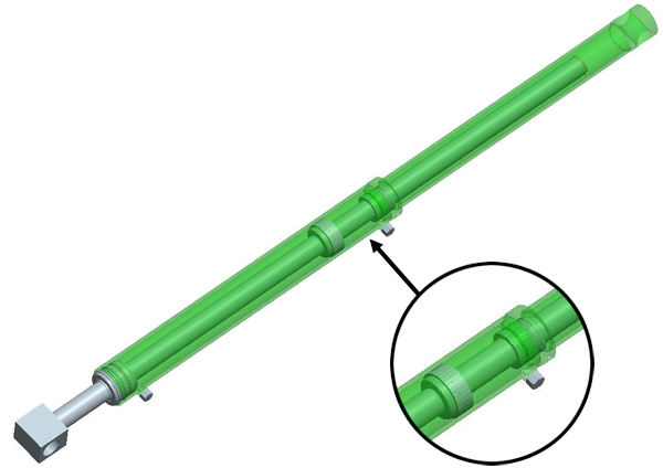 Cilindro con falso vástago

Los tiempos de ciclo rápidos del cucharón son importantes para vaciar la carga del cucharón lo más rápido posible, (con mucha frecuencia) para ser lo más productivo posible, mientras se completan las operaciones de carga. El diseño de cilindro del cucharón puede tener un gran impacto en este tiempo de ciclo, en especial para los cargadores frontales con nivelación automática mecánica.
Por tanto, todos los cargadores frontales MSL de la Serie H y M utilizan cilindros de cucharón de falso vástago. Un cilindro falso vástago tiene un menor requerimiento de desplazamiento de aceite en el extremo del cabezal del cilindro, lo cual permite a este cilindro descargar mucho más rápido que un cilindro normal.
| Altura de elevación máxima | 3816 mm 150 in. |
|||
|---|---|---|---|---|
| Capacidad de elevación a altura completa | Medida en articulación 1667 kg 3674 lb 2636 kgf 5811 lbf |
|||
| Fuerza de salida de la pluma | ||||
| Capacidad de fuerza de retroacción del cucharón | En la línea del nivel del suelo 4515 kgf 9954 lbf |
|||
| Separación a altura completa, con el cucharón bajado | 2781 mm 110 in. |
|||
| Ángulo de vaciado | -53 grados (ángulo) | |||
| Ángulo de retroacción | 42 grados (ángulo) |
| Esquema de especificaciones | Ver esquema |
|---|
| Modelo | 6J 4 cilindros | |||
|---|---|---|---|---|
| Neumáticos delanteros | 12.4R24 | |||
| Neumáticos traseros | 18.4R38 | |||
| Configuración del eje frontal | MDWD | |||
| Distancia entre ejes | 2400 mm 94.5 in. |
|||
| Capacidad de la bomba | 81 L/min 21 gpm |
|||
| Presión nominal | 200 bar 2900 psi |
| Peso base | 1356.8 kg | |||
|---|---|---|---|---|
| Configuración de nivelación | Nivelación automática mecánica (MSL) | |||
| Cucharón utilizado | Materiales de 1850 mm Materiales de 73 in. |
|||
| Peso del cucharón | 236 kg 520 lb |
|||
| Capacidad de elevación a altura completa | Medida en articulación 1667 kg 3674 lb Medida a 800 mm por delante de la articulación 1827 kg 4026 lb |
|||
| Capacidad de elevación a 1500 mm (59 in.) | Medida en articulación 2150 kg 4738 lb Medida a 800 mm por delante de la articulación 2057 kg 4533 lb |
|||
| Fuerza de salida de la pluma | Medida en articulación 2636 kgf 5811 lbf Medida a 800 mm por delante de la articulación 2299 kgf 5067 lbf |
|||
| Capacidad de fuerza de retroacción del cucharón | A altura máxima 2270 kgf 5003 lbf A una altura de elevación 59 in. (1500 mm) 4396 kgf 9691.5 lbf En la línea del nivel del suelo 4515 kgf 9954 lbf |
|||
| Dimensiones | Altura de elevación máxima 3816 mm 150 in. A altura completa, a nivel del cucharón 3618 mm 143 in. A altura completa, con el cucharón bajado 2781 mm 110 in. |
|||
| Longitud total | 4886 mm 193 in. |
|||
| Profundidad de excavado | -59 mm -2.3 in. |
|||
| Alcance | A altura máxima 953 mm 38 in. A nivel del suelo, nivel del cucharón 2486 mm 98 in. |
|||
| Ángulo del cucharón | Ángulo de vaciado -53 degree (angle) Ángulo de retroacción 42 degree (angle) Ángulo de vaciado al suelo -94 degree (angle) |
|||
| Tiempos de ciclo | Elevación de cargadora 4.9 seconds Descenso de cargadora 3.6 seconds Volteo de cucharón 3.8 seconds Retracción de cucharón 3.8 seconds |
|||
| Altura total en posición de transporte |
| Fecha de la Información |
|---|
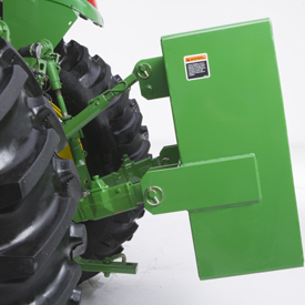
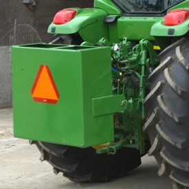
Large ballast box is available to carry additional ballast for greater tractor stability.
Capacities |
|||
Weight |
Sand (Dry) |
Concrete |
Portland Cement |
BW15852 Large ballast box: |
|||
| Volume | 13.3 ft3 = 377L |
||
Material |
581 kg (1277 lb) |
871 kg (1915 lb) |
1089 kg (2395 lb) |
Empty box |
155 kg (342 lb) |
155 kg (342 lb) |
155 kg (342 lb) |
Total |
736 kg (1619 lb) |
1026 kg (2257 lb) |
1244 kg (2737 lb) |
BW15852 Large ballast box is compatible with Category 2 Quik-Couplers and Category 2 or 3 hitches.
See ''Rear Ballast Requirements'' for proper ballasting of the tractor.
General Purpose (GP) buckets
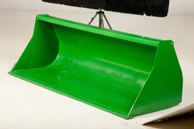 Materials bucket

Materials buckets may be used for loading dirt, gravel, feed, and light materials as well as scraping, digging, and other general-purpose tasks.
NOTE: Materials buckets are not compatible with replaceable cutting edges or digging teeth.
This general-purpose bucket can be used in numerous applications.
The high-volume bucket is intended for use with lighter-density high-volume materials. The bucket capacity makes this an effective tool for handling snow, wood shavings, and other loose materials.
 Materials bucket

Materials buckets may be used for loading dirt, gravel, feed, and light materials as well as scraping, digging, and other general-purpose tasks.
NOTE: Materials buckets are not compatible with replaceable cutting edges or digging teeth.
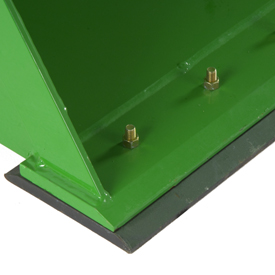 Replaceable wear edge

For those who frequently scrape on concrete, a replaceable cutting edge will greatly extend the life of the bucket:
 Replaceable wear edge

For those who frequently scrape on concrete, a replaceable cutting edge will greatly extend the life of the bucket:
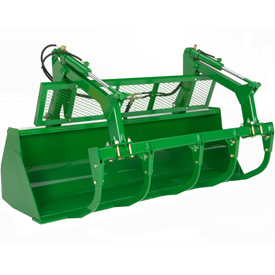 Five-tine round bale/silage grapple with grille

All compatible John Deere Loaders use the same five-tine, pin-on grapple. The advantages of this grapple are:
High-performance operators will choose the five-tine grapple for its increased durability and load-carrying capacity. Advantages include:
The grapple is equipped with twin cylinders to provide excellent clamping force.
NOTE: The center tine of the five-tine grapple is slightly off center to avoid contact with the placement of optional digging teeth.
NOTE: The grapple is not compatible with materials or high-volume buckets.
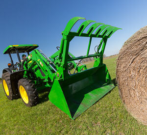 1850-mm (73-in.) bale grapple bucket
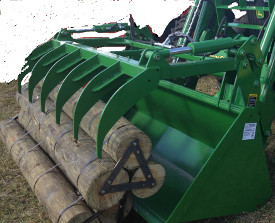 73–in. (1850 mm) grapple bucket BW15358 shown (all one piece
The bale grapple bucket is a complete solution ideal for full loads of silage, handling bales, or cleaning up debris or manure.
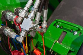 Two function quick coupler

The H240, H260, H310, H340, and H360 Loaders feature two-function quick-couplers in base machine. To disconnect the hydraulic connection between the loader and the tractor, it is necessary to relieve the hydraulic system oil pressure on the tractor.
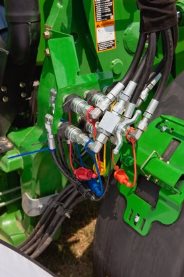 Three function quick coupler
The H240, H260, H310, H340, and H360 Loaders can be equipped with three-function quick-couplers. Hoses will be installed in the boom arm and just the couplers will need to be assembled along with the third-function bracket and oil line. To disconnect the hydraulic connection between the loader and the tractor, it is necessary to relieve the hydraulic system oil pressure on the tractor.
The hood guard's basic function is to:
Compatibility:
It is highly recommended to purchase a front weight bracket when using a loader. The hood guard is designed to be slightly rearward of the front weight bracket. This is so that the front weight bracket is the first point of contact against lower stationary objects.
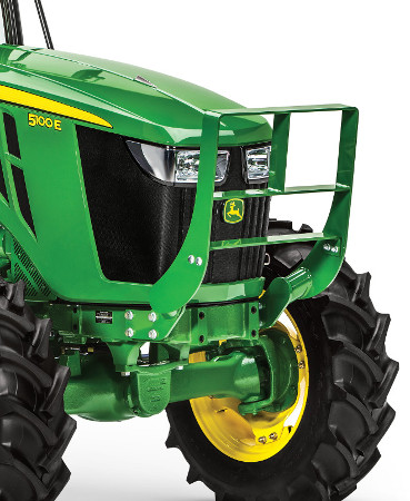 Hood guard on 5100E Tractor

The hood guard’s basic function is to:
It is highly recommended to purchase a front weight bracket when using a loader. The hood guard is designed to be slightly rearward of the front weight. This is so that the front weight is the first point of contact against lower stationary objects.
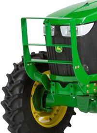 Hood guard for 5E 4-cylinder and 5M Series Tractors
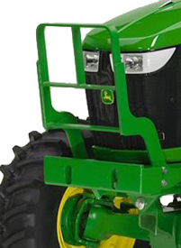 Hood guard for 6D and 6E Series Tractors
The heavy-duty hood guard is compatible with 5E 4-cylinder, 5M, 6D, and 6E Tractors.
NOTE: See below for details on tractor family, series, and model years.
The basic function of a hood guard is to:
The hood guard:
It is highly recommended to purchase a front weight bracket when using a loader. The hood guard is designed to be slightly rearward of the front weight bracket. This is so the front weight bracket is the first point of contact against lower stationary objects.
If a front weight bracket is not used, the lower bar can be moved downward to improve the protection of the grille below the lights.
The loader hoses are connected to the mid-tractor selective control valves (SCVs).
The loader hoses are connected to the mid-tractor selective control valves (SCVs).
The loader hoses are connected to the mid-tractor selective control valves (SCVs).
 Two function quick coupler

The H240, H260, H310, H340, and H360 Loaders feature two-function quick-couplers in base machine. To disconnect the hydraulic connection between the loader and the tractor, it is necessary to relieve the hydraulic system oil pressure on the tractor.
 Three function quick coupler
The H240, H260, H310, H340, and H360 Loaders can be equipped with three-function quick-couplers. Hoses will be installed in the boom arm and just the couplers will need to be assembled along with the third-function bracket and oil line. To disconnect the hydraulic connection between the loader and the tractor, it is necessary to relieve the hydraulic system oil pressure on the tractor.
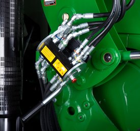 Single-point hydraulic connection on row crop tractor
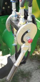 Single-point hydraulic connection on 5E Series Tractor
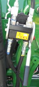 Single-point hydraulic connection on 5M Series Tractor
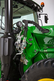 Single-point hydraulic connection with rigid lines on FT4 6R large frame
The H240, H260, H310, H340, and H360 Loaders feature a single-point hydraulic connection that also incorporates the connection point for any electrical needs as well. To disconnect the hydraulic connection between the loader and the tractor, it is necessary to relieve the hydraulic system oil pressure on the tractor.
 Single-point hydraulic connection on row crop tractor
 Single-point hydraulic connection on 5E Series Tractor
 Single-point hydraulic connection on 5M Series Tractor
 Single-point hydraulic connection with rigid lines on FT4 6R large frame
The H240, H260, H310, H340, and H360 Loaders feature a single-point hydraulic connection that also incorporates the connection point for any electrical needs as well. To disconnect the hydraulic connection between the loader and the tractor, it is necessary to relieve the hydraulic system oil pressure on the tractor.
 Single-point hydraulic connection on row crop tractor
 Single-point hydraulic connection on 5E Series Tractor
 Single-point hydraulic connection on 5M Series Tractor
 Single-point hydraulic connection with rigid lines on FT4 6R large frame
The H240, H260, H310, H340, and H360 Loaders feature a single-point hydraulic connection that also incorporates the connection point for any electrical needs as well. To disconnect the hydraulic connection between the loader and the tractor, it is necessary to relieve the hydraulic system oil pressure on the tractor.
 Single-point hydraulic connection on row crop tractor
 Single-point hydraulic connection on 5E Series Tractor
 Single-point hydraulic connection on 5M Series Tractor
 Single-point hydraulic connection with rigid lines on FT4 6R large frame
The H240, H260, H310, H340, and H360 Loaders feature a single-point hydraulic connection that also incorporates the connection point for any electrical needs as well. To disconnect the hydraulic connection between the loader and the tractor, it is necessary to relieve the hydraulic system oil pressure on the tractor.
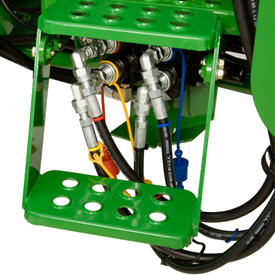 2-function hoses and couplers
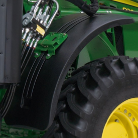 Stationary fender (H480 shown)

Loader stationary fenders are highly recommended for those operating in conditions where the front axle will be in full oscillation and turn frequently or where tight turns are made while maneuvering through gates or obstacles that will catch tractor axle-mounted fenders.
The loader stationary fenders still provide coverage for debris from the tire, but they do not protrude to become damaged in operation. The fenders can be removed to enable better access for servicing as well.
 Stationary fender (H480 shown)

Loader stationary fenders are highly recommended for those operating in conditions where the front axle will be in full oscillation and turn frequently or where tight turns are made while maneuvering through gates or obstacles that will catch tractor axle-mounted fenders.
The loader stationary fenders still provide coverage for debris from the tire, but they do not protrude to become damaged in operation. The fenders can be removed to enable better access for servicing as well.
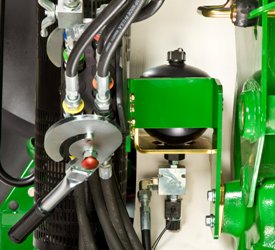 Nitrogen-charged accumulator and electric valve
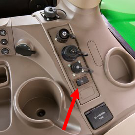 Operator on/off switch
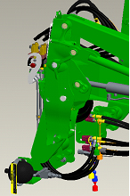 LSS on H180
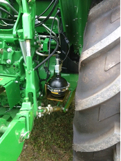 LSS on 5E and 5M
An enhancement to the loader is the suspension system. A great level of loader productivity is achieved with the LSS.
Performance
NOTE: Check bale-handling capability of tractor before use.
Cost of ownership
Reasons for turning LSS off include:
The switch is conveniently located in the operator station to avoid having to exit the tractor seat to manually move the handle on the LSS.
LSS can also be ordered with a manual shutoff. Depending on the tractor/loader model, the accumulator is located in different places. On the 440R, the accumulator is mounted outside the bottom of the mounting frame. On the 5 Series Tractors, the accumulator is mounted near the inside of the rear right wheel. On 6 Series tractors and larger, it is mounted in between the hydraulic connection and the mounting frame.
 Nitrogen-charged accumulator and electric valve
 Operator on/off switch
 LSS on H180
 LSS on 5E and 5M
An enhancement to the loader is the suspension system. A great level of loader productivity is achieved with the LSS.
Performance
NOTE: Check bale-handling capability of tractor before use.
Cost of ownership
Reasons for turning LSS off include:
The switch is conveniently located in the operator station to avoid having to exit the tractor seat to manually move the handle on the LSS.
LSS can also be ordered with a manual shutoff. Depending on the tractor/loader model, the accumulator is located in different places. On the 440R, the accumulator is mounted outside the bottom of the mounting frame. On the 5 Series Tractors, the accumulator is mounted near the inside of the rear right wheel. On 6 Series tractors and larger, it is mounted in between the hydraulic connection and the mounting frame.
 Nitrogen-charged accumulator and electric valve
 Operator on/off switch
 LSS on H180
 LSS on 5E and 5M
An enhancement to the loader is the suspension system. A great level of loader productivity is achieved with the LSS.
Performance
NOTE: Check bale-handling capability of tractor before use.
Cost of ownership
Reasons for turning LSS off include:
The switch is conveniently located in the operator station to avoid having to exit the tractor seat to manually move the handle on the LSS.
LSS can also be ordered with a manual shutoff. Depending on the tractor/loader model, the accumulator is located in different places. On the 440R, the accumulator is mounted outside the bottom of the mounting frame. On the 5 Series Tractors, the accumulator is mounted near the inside of the rear right wheel. On 6 Series tractors and larger, it is mounted in between the hydraulic connection and the mounting frame.
 Nitrogen-charged accumulator and electric valve
 Operator on/off switch
 LSS on H180
 LSS on 5E and 5M
An enhancement to the loader is the suspension system. A great level of loader productivity is achieved with the LSS.
Performance
NOTE: Check bale-handling capability of tractor before use.
Cost of ownership
Reasons for turning LSS off include:
The switch is conveniently located in the operator station to avoid having to exit the tractor seat to manually move the handle on the LSS.
LSS can also be ordered with a manual shutoff. Depending on the tractor/loader model, the accumulator is located in different places. On the 440R, the accumulator is mounted outside the bottom of the mounting frame. On the 5 Series Tractors, the accumulator is mounted near the inside of the rear right wheel. On 6 Series tractors and larger, it is mounted in between the hydraulic connection and the mounting frame.
 Nitrogen-charged accumulator and electric valve
 Operator on/off switch
 LSS on H180
 LSS on 5E and 5M
An enhancement to the loader is the suspension system. A great level of loader productivity is achieved with the LSS.
Performance
NOTE: Check bale-handling capability of tractor before use.
Cost of ownership
Reasons for turning LSS off include:
The switch is conveniently located in the operator station to avoid having to exit the tractor seat to manually move the handle on the LSS.
LSS can also be ordered with a manual shutoff. Depending on the tractor/loader model, the accumulator is located in different places. On the 440R, the accumulator is mounted outside the bottom of the mounting frame. On the 5 Series Tractors, the accumulator is mounted near the inside of the rear right wheel. On 6 Series tractors and larger, it is mounted in between the hydraulic connection and the mounting frame.
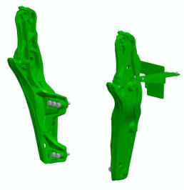 5M mounting frame
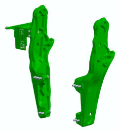 5M mounting frame
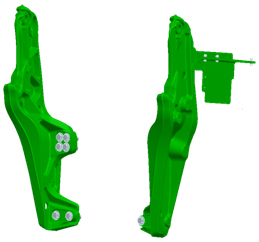 6E Final Tier 4 (FT4)
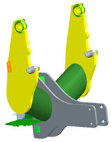 5E 4 Cylinder (IT4; 5085E, 5100E) mounting frame
Mounting frames are designed to evenly distribute forces during loader operation. Hardware is accessible to torque to the correct specifications.
 5M mounting frame
 5M mounting frame
 6E Final Tier 4 (FT4)
 5E 4 Cylinder (IT4; 5085E, 5100E) mounting frame
Mounting frames are designed to evenly distribute forces during loader operation. Hardware is accessible to torque to the correct specifications.
Digging teeth can be added to the heavy-duty bucket. This feature allows for easier digging in hard ground or breaking loose hard-packed materials, such as manure or silage. Digging teeth are not compatible with replaceable cutting edges.